In the previous post we looked at the operation of the PWM hardware on the Pico. In this post we'll look at the ADC - analogue to digital conversion.
Although the Pico has several (potential) ADC input pins, it only has one converter: it can only conduct one conversion at a time, though it can take successive samples from different pins. It has a resolution of 12 bits (giving an output range of 0-4095).
The way the converter works is that when you request a measurement, a "sample and hold" circuit takes a snapshot of the input voltage on the currently-selected input pin. There is then a process of successive approximation as the input voltage is compared against various fractions of a reference voltage until, after 96 cycles of the clock, the hardware comes up with its best estimate of the input value. By default, the ADC is driven by a 48MHz clock, allowing up to 500,000 samples per second.
At its simplest, you can simply ask the hardware for a reading and your code will block until the value is available. However, there is also a hardware FIFO which can be used as a buffer for up to 4 results and it's also possible to have the hardware use DMA to write a sequence of results to memory autonomously. Both the FIFO and DMA can generate interrupts when the measurement(s) are complete.
The program below is a little more complicated than necessary, but it illustrates the use of the FIFO which could potentially allow other work to take place while the reading is in progress.
There are 3 GPIO pins that can be configured as ADC inputs, starting at GPIO 26, often referred to as channels 0, 1 and 2; in this case we're going to use channel 0. At line 18 we configure the corresponding GPIO pin to be used for ADC. We then initialise the ADC hardware (line 20), select channel 0 as the input (line 21). We then set up some configuration options (line 22): in this case we're going to use the FIFO but not DMA, we're not using interrupts but we have the option of determining how many samples are in the FIFO before an interrupt is raised (in this case one), we ask the hardware to set the top bit of the sample value if an error occurred and as we want full accuracy we ask for the samples not to be truncated to 8 bits. In line 28 we choose to use the default clock - we can choose a slower clock if we want (useful for taking repeated samples at a manageable rate).
One function missing from the SDK is a means of causing the ADC to take one sample asynchronously (there's one to take repeated samples), so we define one at line 9. When the ADC is started it will sample the input and report the value in the FIFO when the conversion is completed.
At line 35 we request a sample and could potentially do other work while the ADC goes through its 96 cycles of approximation. The function adc_fifo_get_blocking() will wait until the ADC is finished and return the sample value. The value is printed at line 39 and another sample is requested at line 42.
1 2 3 4 5 6 7 8 9 10 11 12 13 14 15 16 17 18 19 20 21 22 23 24 25 26 27 28 29 30 31 32 33 34 35 36 37 38 39 40 41 42 43 44 45 46 | // Sample programme to use Pico ADC #include "pico/stdlib.h" #include <stdio.h> #include "hardware/adc.h" #define CAPTURE_CHANNEL 0 void adc_oneshot() { hw_set_bits(&adc_hw->cs, ADC_CS_START_ONCE_BITS); } int main() { uint16_t adc_val ; stdio_init_all(); adc_gpio_init(26 + CAPTURE_CHANNEL); adc_init(); adc_select_input(CAPTURE_CHANNEL); adc_fifo_setup( true, // Use FIFO false, // Disable DMA 1, // Queue depth at which IRQ is triggered (not used) true, // Set error bit if failure false); // Use full 12-bit samples adc_set_clkdiv(0); // Use default clock sleep_ms(5000); printf ("Starting\n"); sleep_ms(3000); adc_oneshot(); // Take one sample while (1) { adc_val = adc_fifo_get_blocking(); // Wait for sample to be available printf ("ADC Value is %d\n", adc_val); // Display sample value sleep_ms(5000); adc_oneshot(); // Initiate next sample tight_loop_contents(); } } |
We can wire up the Pico with a simple voltage divider circuit:
The values of R1 and R2 aren't too important (as long as they're not so small as to draw excessive current). Vref goes to the Pico's ADC reference voltage (pin 35, nominally 3.3V), AGrnd to the analogue ground (pin 33) and ADC Sample to the input pin (pin 31).
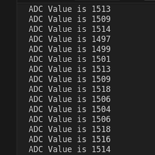
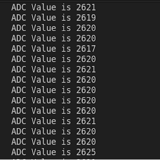
If you do this and run the program above, you'll get an output similar to this (though the values will depend on the resistors):
There are some minor variations in the sample values, but it's only around 2mV. If you do the same thing but connect the top of R1 to Pin 35 instead (the Pico's 3.3V output), you get slightly higher and more irregular readings:
The variation is about an order of magnitude bigger and the readings are all marginally higher. This is because the Pico's ADC reference voltage is slightly better stabilised than the "regular" 3.3V output and consequently at a marginally lower voltage.
If we make R1 smaller, the ADC sample voltage will go up and if you rerun the program you'll get a higher reading:
If you were to connect the ADC sample input to ground, you would expect the ADC to read 0, but this is in fact not the case:
A consequence of the design of the circuitry is that there's a small offset in the measurement so the readings have a floor slightly above zero, representing roughly 0.01V though this will vary between devices. These inaccuracies are negligible for our purposes, though higher-precision measurements may need to compensate for them.
So, at the end of this post, we can see that we not only have the means to generate a PWM signal of our choosing, we can also measure voltages with an accuracy that's probably acceptable for our purposes.
In the next post we'll look at using the output of the ADC to control the PWM signal and thereby have the rudiments of a switched-mode power supply.


Comments
Post a Comment